SO Dovetail
This dovetail joint is designed for the Shaper Origin, by allowing for the radiused inside corners that the SO generates. Unlike a traditional dovetail jig, the pins, tails and spacing can be completely controlled to any dimension.
Parameters
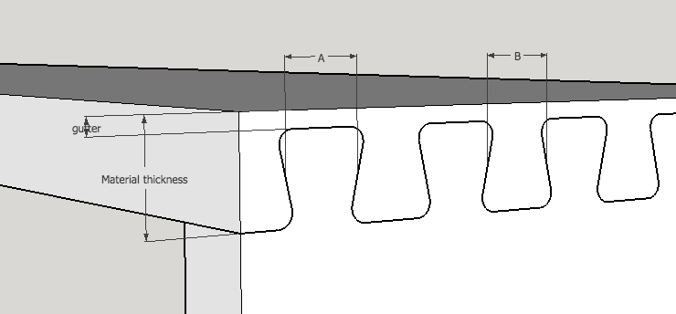
The diagram shows some of the parameters. The material thickness is the thickness of the material receiving the pins. In a typical drawer dovetail, this would be the drawer front. In that example, the sides could be a different thickness. This only affects how deep the pockets around the pin are cut, so the other thickness does not change the generated SVG.
The pin width and tail width are set for the midpoint of the pin and tails. For a given joint length these are scaled to give an exact integer number of pins. So for a given application, the pin and tail size may be set for a desired aesthetic.
This allows for a consistent pin and tail size for several different size drawers, for example.
The pin angle represents the slope of the pins, in degrees. Typical values are between 8 and 15 degrees.
Blind Dovetails
When a non-zero gutter is provided, the pins pockets between the tails will be set back from the face giving a blind doetail.


Through Dovetails
When the gutter is set to 0.0, the created joint will now be a through-dovetail.


Now the outside edge of the pins is a sharp angle, since it does not have to mate with a radiused curve on a pin pocket between tails. However, now the pocket cut for the pin must extend beyond the edge material boundary, to allow the SO to remove the complete pin profile after allowing for the bit radius.
File names
The two files are named suggestively. The first named '...pinface...' is used to cut the joint pins. This is laid out onto the face of the material, for example the drawer sides. Even for blind dovetails, you would tyically align the end of the pin with the end of the material. *So the current alignment guides for the pins is not optimal.
Similarly, the '...tailedge...' image is intended to cut the tails, by pocketing out the image of the pins from the board edge. So this requires something like the vertical workstation. Now the blue rectangle represents the border that should be aligned to the board edge.
Alignment
Because the SO provides no way to indicate prefered alignment points, and because the pocket region must go beyond this boundary to allow the bit to completely pocket out the tails, a separate alignment guide (the dashed line) is provided. This is 0.5" (or 1 cm.) away from the actual desired alignment, which should allow proper alignment for typical grid settings.